PLC Programming
http://www.contactandcoil.com/patterns-of-ladder-logic-programming/five-rung/
Most or all new PLCs can be programmed in multiple languages, from the IEC-61131-3 specification. These languages are different, and the idiomatic way to do something in one language isn’t necessarily the way to do it in another language. For instance, doing any kind of loop (for, while) is non-idiomatic in ladder logic, but is certainly an idiomatic construct in structured text. That means part of our job as programmers is to pick the correct language to express our intent.
Data collection, string parsing, and math is naturally expressed in structured text (ST), but control logic is naturally expressed in ladder diagram (LD). Part tracking logic can go either way. Sequential function chart (SFC) is perfect for expressing a sequence, ladder diagram is a good runner up using the Step Pattern, and structured text requires that you define a state machine, which is the least expressive option.
Patterns of Ladder Logic Programming
This section outlines common ladder logic programming patterns, similar to design patterns for most programming languages. Familiarity with these patterns will improve your programming speed, enhance code readability, and provide standardized solutions to recurring challenges
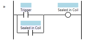
Sealed in Coil
The Sealed in Coil pattern in Ladder Logic Programming uses a trigger condition and a coil. Once the coil is energized, a contact from the coil keeps it "sealed in", never turning off unless the PLC has a hard reset, effectively remembering the state has occured at least once since the program has been running. This pattern is useful for situations where you need to remember that an event has occurred, such as homing a machine.
http://www.contactandcoil.com/wp-content/uploads/Sealed-in-Coil.png
State/Fault Coil
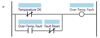
The State Coil (or Memory Coil) pattern in Ladder Logic Programming builds on the Sealed in Coil. It includes a trigger to energize the coil, a contact to seal it in, and a trigger/condition to break the seal. This pattern is often used to represent faults, remembering the fault condition until it is cleared and reset.
If the fault condition is still "active", the coil will stay de-energized. In other words, "a fault must be cleared before it can be reset".
http://www.contactandcoil.com/wp-content/uploads/State-Coil-Over-temperature-Fault.png
Start/Stop Circuit
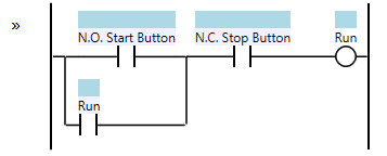
The Start/Stop Circuit in Ladder Logic Programming is similar to the State Coil, and prioritizes the Stop condition (similar to Fault). This means if both Start and Stop are active, Stop overrides Start. This is crucial for safety, especially if the Start condition malfunctions. The circuit is typically used with a normally open Start momentary button and a normally closed Stop momentary button, ensuring that a Stop signal is sent if the Stop button wiring fails.
http://www.contactandcoil.com/wp-content/uploads/Start-Stop-Circuit-NC-Stop-Button.png
Set/Reset (Anti-)Pattern
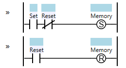
The Set/Reset (Latch/Unlatch) pattern in Ladder Logic Programming provides persistent memory, remembering state even after power loss. It mimics a physical latching relay, using Set and Reset coils to control the state of a memory bit. While powerful, it's often misused by scattering Set/Reset coils throughout the logic, making it hard to understand. Best practice is to use a single Set and Reset coil per memory bit, ideally on adjacent rungs, for clarity and maintainability. This pattern is essential for applications like part tracking where state needs to be preserved across power cycles.
http://www.contactandcoil.com/wp-content/uploads/Set-Reset.png
Note: Unlike PLC coils that simulate relays and lose state on power loss, digital latches (flip-flops) in microchips also lose state without power. PLCs use various methods like battery-backed SRAM or persistent storage to retain memory during power outages.
Flasher Pattern
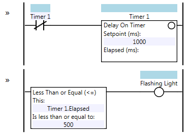
The Flasher pattern in Ladder Logic Programming creates a flashing light using timers. The two-timer variant uses two timers with 500ms delays to alternate between on and off states. The one-timer variant achieves the same result with a single timer and a comparison instruction, offering slightly better accuracy. Both variants are affected by PLC scan times, which can introduce variability in the flashing frequency. For higher accuracy, consider using high-speed tasks or timer interrupts.
http://www.contactandcoil.com/wp-content/uploads/Flasher-Two-Timer-Variant.png
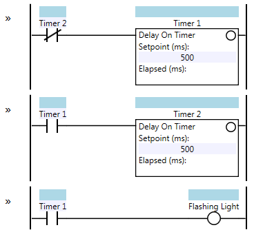
- Two timer solution
Imagine two timers taking turns to flip a light switch.
- Timer 1 starts the cycle: It runs for 500 milliseconds (half a second).
- Timer 1 is done with cycle and its output contact turns on.
- Timer 1's output contact turns on the light and starts Timer 2
- Timer 2 runs: Timer 2 also runs for 500ms.
- Timer 2's output coil starts Timer 1 and turns off light.
- On next scan, Timer 2 is idle
Now, both timers are back to zero, and Timer 1 starts again, repeating the whole process. This creates a flashing light that's ON for 500ms and OFF for 500ms.
Think of it like a relay race: Timer 1 runs its part, then passes the baton to Timer 2, who runs its part and passes the baton back to Timer 1. This keeps happening, making the light flash on and off.
http://www.contactandcoil.com/wp-content/uploads/Flasher-One-Timer-Variant.png
Step Pattern
TODO - Needs to be better explained
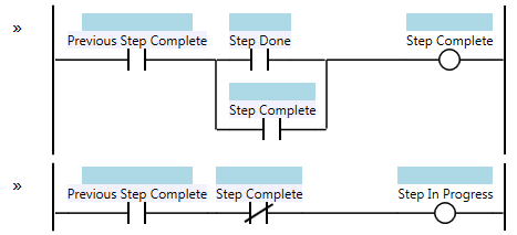
The Step pattern is fundamental for creating sequential operations in Ladder Logic Programming. Each step has an "In Progress" coil that activates when the previous step is complete and a "Done" condition that triggers the next step. Multiple steps form a sequence, executing one after another. This pattern is often used with the Mission pattern for more complex tasks. Variations of the Step pattern include forcing a step to be active for at least one scan or creating "one-shot" steps that execute for a single scan.
http://www.contactandcoil.com/wp-content/uploads/Step.png
Modbus Control of VFD
Command Source Frequency Source Modbus Config
Modbus
Modbus is an industrial protocol that was developed in 1979 to make communication possible between automation devices.
Originally implemented as an application-level protocol intended to transfer data over a serial layer, Modbus has expanded to include implementations over serial, TCP/IP, and the user datagram protocol (UDP). This document provides an in-depth view of the protocol implementation.
Modbus is a request-response protocol implemented using a master-slave relationship. In a master-slave relationship, communication always occurs in pairs—one device must initiate a request and then wait for a response—and the initiating device (the master) is responsible for initiating every interaction. Typically, the master is a human machine interface (HMI) or Supervisory Control and Data Acquisition (SCADA) system and the slave is a sensor, programmable logic controller (PLC), or programmable automation controller (PAC). The content of these requests and responses, and the network layers across which these messages are sent, are defined by the different layers of the protocol.
Modbus TCP Overview
The Modbus TCP protocol uses a Client/Server architecture for data exchange.
- Clients are devices that initiate any data exchange with other devices on the network. This applies to both I/O communications and service messaging.
- Servers are devices that address any data requests generated by a Client. This applies to both I/O communications and service messaging.
Modbus Explicit Messaging using GPL for Control Expert
Part 1 - https://youtu.be/r_-tmkiAre8?si=NORQj0WsWjl26Ji_
Part 2 - https://youtu.be/ILjCjr1Oa9k?si=9Wan9oBD9FmJzV7y
Implicit messaging (I/O Scanning as MODBUS Master)
Implicit Messaging is limited to Modbus devices supporting Holding Registers (4x), because the function codes implemented are 3, 16, and 23. Devices that don't support these function codes will require explicit messaging (0x, 1x, and 3x registers).
Function codes used are WRITE_VAR and READ_VAR.
WRITE_VAR
attachment:_20241211_104606screenshot.png

Class 0 codes are generally considered the bare minimum for a useful MODBUS device, as they give the master the ability to read from or write to the data model
Class 0 Codes
attachment:_20241211_105620screenshot.png

attachment:_20241211_105834screenshot.png

The MODICON M580 can support a maximum of 16 simultaneous connections per cycle (at least), you might need to implement logic if you have way more MODBUS connections.
Control Expert Sizes
The difference is in the product that each size supports. Below is a chart. attachment:_20241212_060839screenshot.png

| LED | On | Flashing | Off |
| RUN (green) | PLC running normally, | PLC in STOP mode or | PLC not configured: |
| program executing | blocked by a software error | application missing, | |
| invalid or incompatible | |||
| ERR (red) | Processor or | - PLC not configured | Normal state, |
| or system error | - PLC blocked by a | no internal error | |
| software error | |||
| - PLC bus error | |||
| IO (red) | Input/output errors | Autotest | Normal state, no internal error |
| coming from a module, | |||
| a channel or a | |||
| configuration error | |||
| ETH MS | Green : RUN / STOP | Green : configuration | // |
| red/green | Red : Err or OS update | Red : autotest | |
| ETH NS | Green : RUN / STOP | Green : configuration | // |
| red/green | Red : duplicated IP add | Red : autotest | |
| Red : Err or OS update |
FT01 FT02 FT03 FT04 FT11 FT12 FT21 FT22 FT51 FT52 FT53 FT61 FT62 FT63
| INPUT NAME | INPUT PIN | TYPE | VALUE | OUTPUT Name | Pin Name | Type | Value |
| RAW_IN | AI_FT01_RAW | INT | SCALE_OUT | FTxx_SCL | REAL | ||
| FORCED_IN | FTxx_FORCED_IN | BOOL | INT_ERR | FTxx_INT_ERR | BOOL | ||
| FORCED_SP | FTxx_FORCED_SP | REAL | |||||
| OUT_MIN | FTxx_OUT_MAX | REAL | |||||
| OUT_MAX | FTxx_OUT_MIN | REAL | |||||
| LO_LO_SP | FTxx_LO_LO_SP | REAL | LO_LO_ALM | FTxx_LO_LO_ALM | BOOL | ||
| LO_SP | FTxx_LO_SP | REAL | -1.0 | LO_ALM | FTxx_LO_ALM | BOOL | |
| HI_SP | FTxx_HI_SP | REAL | HI_ALM | FTxx_HI_ALM | BOOL | ||
| HI_HI_SP | FTxx_HI_HI_SP | REAL | HI_HI_ALM | FTxx_HI_HI_ALM | BOOL |